Pulse-Width-Modulation (PWM) for Motor Speed Control

What is PWM and Why Do We Use it for Motor Control?

Pulse Width Modulation (PWM) changes the length of time a pulse is ON or OFF. PWM is used for varied purpose in electronics, but for motor speed control it controls the average power applied to the motor while ensuring peak power is applied to the motor whenever it is turned on. 

Using PWM with an H- Bridge

PWM can be applied to any DC motor. It can be used with an H-Bridge when speed control is required in forward and reverse directions. 

The circuit simulation below uses an Arduino and simplified H-Bridge as motor control.
H-Bridges isolate the motor control signals from the power driving the motor.The Arduino pin 2 turns on transistors A and D; pin 4 turns on B and C.

Current flows through the load resistor from the main supply (+6v) to ground whenever transistors (A or B) and (C or D) are turned on.

This simulation shows Pulse-Width Modulation (PWM) for motor speed control, specifically in a slow start up to full speed. The duty-cycle (ratio of on-to-off time) for each pulse starts at zero, and then is increased by 5% until the motor is turned on fully.

				
					/* Arduino code snippit from an 
iCircuit simulation of PWM with an 
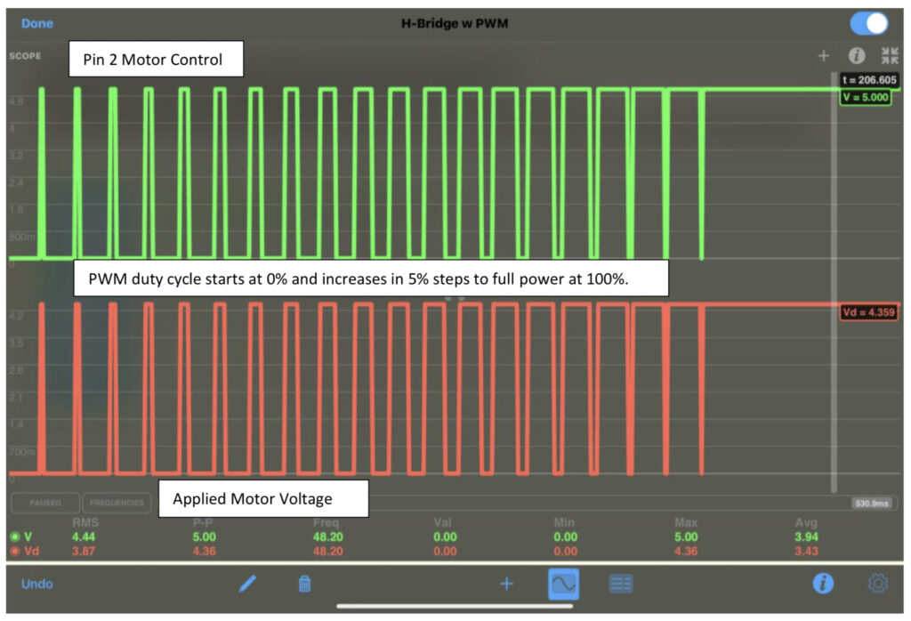
H-Bridge motor driver. 
   -- dgk */

void setup()
{
  pinMode(2, OUTPUT);
  pinMode(4, OUTPUT);
}

void loop()
{
  int pw = 20;
  for (int i=0; i<pw; i++)
  {
    digitalWrite(2, HIGH);
    digitalWrite(4, LOW);
    delay(i);
    digitalWrite(2, LOW);
    delay(pw-i);
  }
  digitalWrite(2, HIGH);
  delay(4*pw);
  digitalWrite(2, LOW);
  delay(4*pw);
  delay(50);
  digitalWrite(4, LOW);
}


PWM Motor Control with Slow-Start to Full Power

Circuit simulation and code snippet by DGKALLGREN; simulation output and figures from iCircuit for iPad by Krueger Systems.