Hardware Setup Procedure
Breadboard Choice
Typical breadboard choices are 830-point and 400-point solderless plugboard such as those shown in Figure 1. Our tutorial uses the 830-point breadboard for its larger surface area; we don’t require so many connection points, but the larger surface area is used to mount the stepper motor driver.
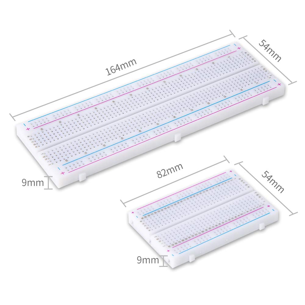
Figure 1 – 830-Point (i.e., the “Long Board”) and 400-Point (“short”) Solderless Breadboards
Power Configuration (MB102 Power Supply)
Many ESP32 peripherals require 5 VDC that should not (MUST not!) be supplied through the ESP32 5 V pin, such as the 28BYJ-48 stepper motor. While the ESP32 operates at 3.3V, it cannot provide enough current to drive a 5 V motor. Use the MB102 power supply to bridge this gap.
- Seat the MB102: Plug the module into the end of the 830-point breadboard.
- Voltage Jumpers: Set the jumper on the side powering the motor to 5V. Set the other side (powering the ESP32) to 3.3V or use the USB cable for the ESP32.
- NOTE: both jumpers in the image are set to 3.3 V; if 5 V is required, move the jumper to the left pair of pins, opposite the 5V label on the board.
- Common Ground: This is the most important step. Connect a jumper wire between the GND rail of the 5V side and the GND rail of the ESP32 side.
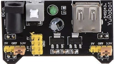
Figure 2 – HiLetgo 5pcs 3.3V 5V Power Supply Module for MB102 Prototype Breadboard DC 6.5-12V or USB Power Supply Module
ESP32 Placement
Many ESP32 development boards (notably those for the ESP32-WROOM chips) are “breadboard-unfriendly” because they are wide.
- Placement: Align the ESP32 so that the pins straddle the center Ravine.
- Note: You may likely only have one row of holes accessible on one side. If you can’t reach the pins, you may need to use male-to-female jumper wires to move the connections to an open area of the board.
Stepper Motor and Driver Board Placement
Placing the stepper motor and driver is problematic in a “quick and dirty” prototype … they can’t mount on the plugboard directly … neither is designed with physical connection for the other. This tutorial uses double
sided tape.
|
|


Figure 3 –28BYJ-48
Stepper Motor and ULN2003 Driver Board.
Component Placement on the Long (i.e., 830-point) Breadboard
With components in place the breadboard should look like
Figure 4.

Figure 4 – Component
Placement on the 830-point Breadboard
“SMOKE TEST”
 | Calling the process steps below a SMOKE TEST is a real caution … If any of these components have not been assembled correctly, this process could lead to electrical damage. Have a partner check your work; if you don’t have a partner to check it, take a moment to re-check your work for errors before you proceed to apply power. |
Power Up the Breadboard
Plug in the 12 VDC power supply into a standard 120 VAC outlet or power strip. Verify that the MB102 is off (i.e., the power button extended and green LED unlit). Plug the coaxial barrel connector into the MB102, push the button until it latches the green LED stays on.
Be alert for any signs of an electrical problem and shut of the power if you suspect any. This is called a SMOKE TEST for a reason
Power Up the RPi400
Turn on and boot the Raspberry Pi 400 if you have not already. Let the boot process complete to show the user desktop.
Connecting the Breadboard/ESP32 and RPi400
Connect the USB cable from the ESP32 board to an available USB port.
N.B., We do this step with breadboard and RPi400 powered to take advantage of the alerts and warnings that may be generated by the RPi400 after the boot process it has completed.
As before, be alert for any problem with the ESP32 or Raspberry Pi 400.
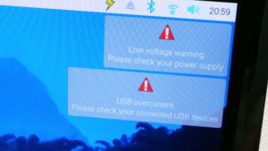
| In particular, be alert for any of these warnings / alerts that may display in the upper right of the desktop: · the USB overcurrent warning on a Raspberry Pi, which indicates the USB devices plugged have exceeded the maximum current the Pi can deliver · the Low Voltage warning, which is an indication that the power supply is unable to maintain the voltage required for operation.
Figure 4 – Alert and Warning Examples for the RPi400. |
“Fire In The Hole”
Start the Arduino IDE program, select Tools->Port, select the correct Port, and select Board Info to confirm that the IDE can communicate with the ESP32 board.
Absent any signs of a problem and with communication between RPi400 and ESP32 board confirmed, proceed to the next steps.
 The Sketch Program
Open Arduino IDE 1.8.19 on your Raspberry Pi 400. Ensure you have selected ESP32 Dev Module under Tools > Board.
The C++ code is given in Table 2.
| Table 1 -Basic 28BYJ-48 Stepper Motor Control Sketch |
|---|
#include <Stepper.h> // The 28BYJ-48 has 2048 steps per full revolution in 4-step sequence const int stepsPerRevolution = 2048; // Initialize the stepper library on pins 13, 14, 12, 27 // Note the sequence 1-3-2-4 for the ULN2003 driver logic Stepper myStepper(stepsPerRevolution, 13, 14, 12, 27); void setup() { // Set the speed to 10-15 RPM (these motors are slow but high torque) myStepper.setSpeed(12); Serial.begin(115200); } void loop() { // Step 1: Rotate Clockwise Serial.println(“Rotating Clockwise…”); myStepper.step(stepsPerRevolution / 2); // Half turn delay(1000); // Step 2: Rotate Counter-Clockwise Serial.println(“Rotating Counter-Clockwise…”); myStepper.step(-stepsPerRevolution / 2); delay(1000); } |
 Control Examples & Logic
Speed Limits
The 28BYJ-48 uses an internal gear reduction ratio of approximately . Because of this:
- Maximum Speed: Usually tops out around 15–20 RPM. Anything higher will cause the motor to vibrate and “stall” without moving.
- Step Precision: Since it takes 2048 steps for one full rotation of the output shaft, each step is approximately .
Power Efficiency
The ULN2003 is a Darlington transistor array. It is reliable but not very power-efficient.
Pro-Tip: If the motor feels hot, it’s because the ULN2003 keeps the coils energized even when stopped. In a real project, you would write a function to set all motor pins to LOW when the motor isn’t moving to save power.
 The Challenge: “The Precision Pendulum”
The Task: Modify the code so the motor acts like a pendulum clock.
- Rotate the motor (512 steps) clockwise.
- Pause for 500ms.
- Rotate the motor (1024 steps) counter-clockwise.
- Pause for 500ms.
- Return to the center ( clockwise).
Bonus Credit: Use the Serial.parseInt() function to allow you to type a specific number of steps into the Serial Monitor on your Pi 400 and have the motor move exactly that distance.
Alternate Design: Using the A4988 Driver Module and NEMA17 Stepper Motor
Transitioning to a NEMA17 motor and an A4988 StepStick is a significant step up in capability. Whether it is a “better” choice depends on the specific goals of your project, as it introduces more power and precision but also requires a bit more care during setup.
The setup is more complex because the NEMA17 stepper motor operates with 12 VDC as its standard supply voltage, with some high-torque models designed to take voltages of 24 VDC or higher. We have a 12 VDC supply as breadboard resource … but it plugs directly into the MB102
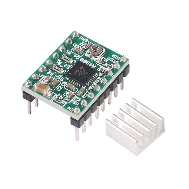 | 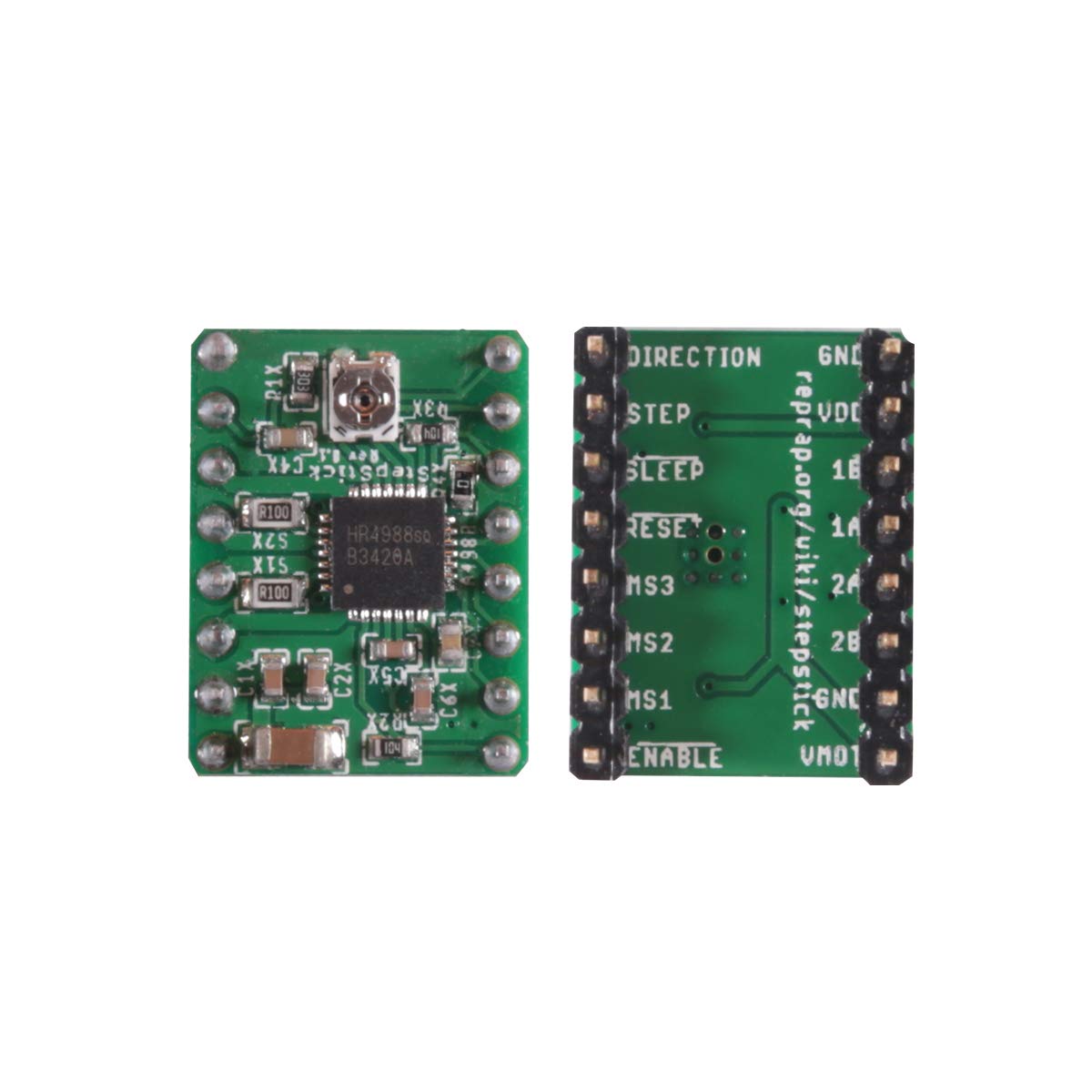 |
A4988 StepStick Stepper Motor Driver Module + Heat Sink for 3D Printer RepRap
A4988 vs. ULN2003: Key Differences
| Table 1 -Differences between the A4988 vs. ULN2003 Stepper Motor Drivers | ||
|---|---|---|
| Feature | ULN2003 (Current Setup) | A4988 StepStick |
| Motor Type | Unipolar (5-wire) | Bipolar (4-wire) |
| Control Method | 4-Phase Sequence (Manual) | Step and Direction (Simplified) |
| Torque | Low (Suitable for small loads) | High (Standard for 3D printers/CNC) |
| Microstepping | None (Full steps only) | Up to 1/16 step (Smoother motion) |
| Current Control | None | Adjustable via Potentiometer |
Using NEMA17 with A4988
The A4988 is specifically designed to drive bipolar motors like the NEMA17. However, there are three critical considerations for this setup:
Simplified Control Logic
Instead of managing a four-pin sequence, the A4988 only requires two pins from the ESP32: STEP (to move) and DIR (to choose direction). This frees up GPIO pins and simplifies the code significantly.
Power Requirements
A NEMA17 motor generally requires higher voltage for optimal performance—usually 12VDC to 24VDC. This poses difficulties in the breadboard where only 5 VDC and 3.3 VDC are readily available.
- VMOT (Power): Connect your 12VDC supply directly to the VMOT and GND pins on the A4988. Avoid running this through the MB102 regulator, as NEMA17 motors can draw more current than the breadboard supply’s voltage regulator can handle.
- VDD (Logic): Connect this to the 3.3V rail of the ESP32. The A4988 logic is compatible with 3.3V signals.
Current Limiting (Crucial)
Unlike the ULN2003, the A4988 must be “tuned.” If you provide too much current, you can burn out the motor or the driver.
- There is a tiny potentiometer on the A4988.
- You must measure the Vref (voltage at the potentiometer) with a multimeter and adjust it to match the rated current of your specific NEMA17 motor.
Updated Sketch for A4988
Because the A4988 uses Step/Direction logic, you can use the AccelStepper library for more advanced control, or use this basic manual method:
| Table 1 -Basic 28BYJ-48 Stepper Motor Control Sketch |
|---|
C++ const int stepPin = 13; const int dirPin = 12; void setup() { pinMode(stepPin, OUTPUT); pinMode(dirPin, OUTPUT); } void loop() { digitalWrite(dirPin, HIGH); // Set direction clockwise // Spin the motor 200 steps (one full rotation for most NEMA17s) for(int x = 0; x < 200; x++) { digitalWrite(stepPin, HIGH); delayMicroseconds(1000); // Controlling speed via pulse width digitalWrite(stepPin, LOW); delayMicroseconds(1000); } delay(1000); } |
Which Design Is “Better”
If the goal is to demonstrate industrial-standard motion control, the A4988/NEMA17 combo is superior. It introduces concepts like microstepping and current regulation.
If the goal is mechanical simplicity and safety, the 28BYJ-48/ULN2003 is often preferred because it is “plug-and-play” and the lower torque makes it less likely to cause damage or heat issues if wired incorrectly.
If noise is a concern, you might also look into the TMC2208 or TMC2209 drivers. They are pin-compatible with the A4988 but use “StealthChop” technology to make the motor movements almost completely silent.
Summary
In the classroom, the 28BYJ-48 is usually the “Goldilocks” choice—it’s safe, inexpensive, and those tiny LEDs on the ULN2003 board provide excellent visual feedback for the students to see the stepping sequence in action.
- If you have MacOS or Windows computers, you may use a later IDE version. Arduino IDE development for the ARM processors in Raspberry Pi systems ended with legacy version 1.8.19. ↑