The RPi 400 Hardware Handshake
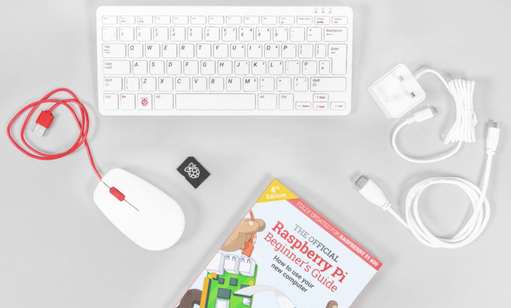
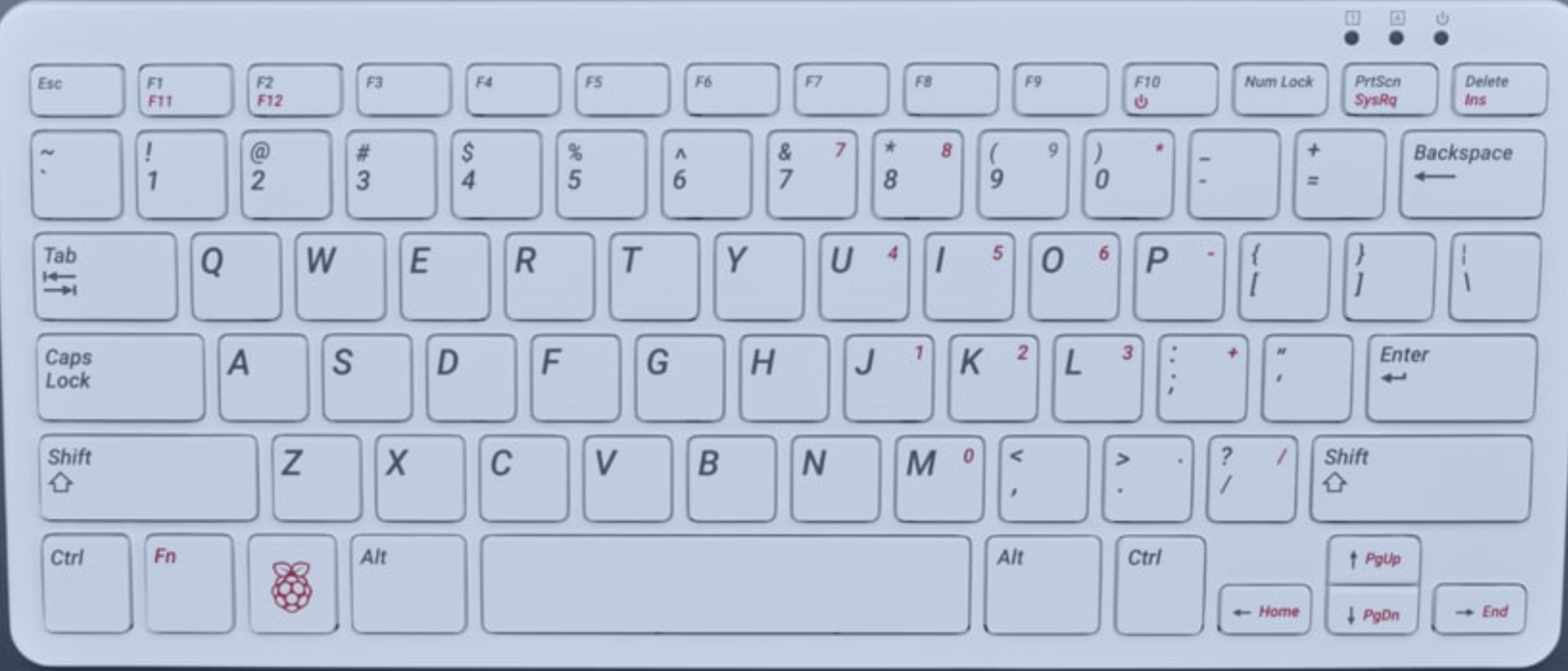
The Raspberry Pi 400 is unique because the computer is inside the keyboard. All the “action” happens on the back edge.
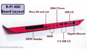
GPIO — General Purpose Input Output
HDMI — High Definition Media Interface
USB — Universal Serial Bus
SD Card — Storage
- Connect the Mouse: Plug the USB mouse into any of the three USB ports (the blue or black rectangular slots) on the back of the keyboard.
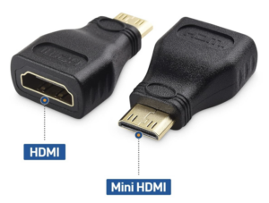
- Connect the Monitor: Plug the Micro-HDMI cable into the port labeled HDMI 0 (it’s the one closest to the microSD card slot). Connect the other end to your monitor.
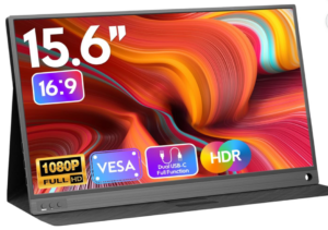
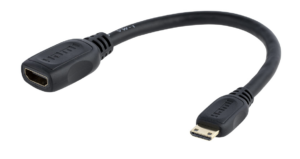
Your monitor may have a Mini-HDMI interface and require an adapter.
- Power On: Plug the USB-C power supply into the leftmost port. The RPi 400 doesn’t have a traditional “On” switch; it will boot as soon as it has power.
- Tip: If it doesn’t wake up, hold Fn + F10 (the power key) for two seconds.
Hardware Setup Procedure
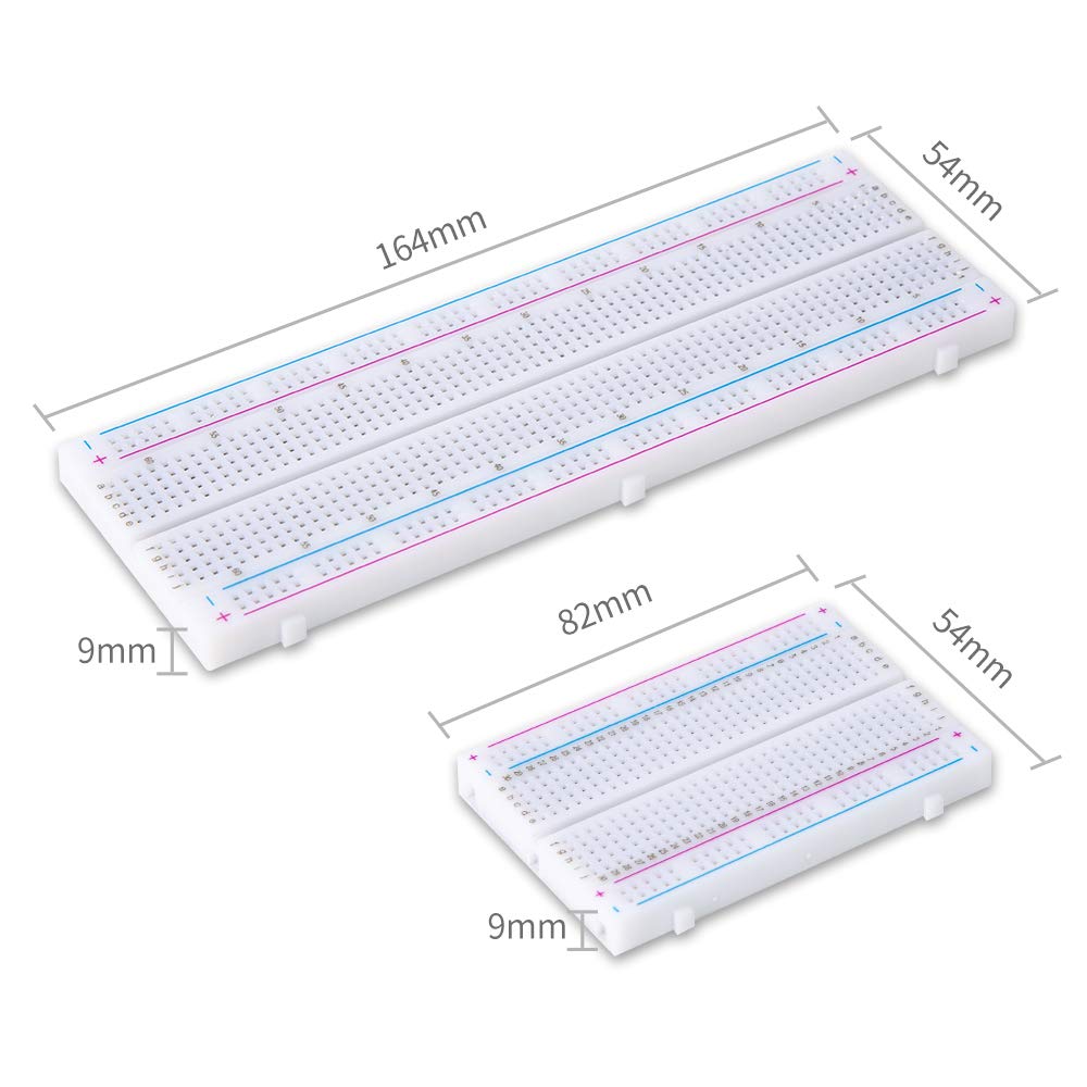
Breadboard ChoiceTypical breadboard choices are 830-point and 400-point solderless plugboard such as those shown. Projects that require few external and that may be powered safely through the microcontroller unit (e.g., an MCU such as an ESP32 or Arduino) may use the 400-point board. Use the 830-point breadboard for its larger surface area to which peripherals can be attached. The 830-point board is particularly useful when additional power is required for motors (whether servos, DC motors, or steppers) that cannot be supplied directly through the MCU, and we need to add a power supply board. |
|
Power Configuration (MB102 Power Supply)
Many ESP32 peripherals require 5 VDC that should not (MUST not!) be supplied through the ESP32 5 V pin, such as the 28BYJ-48 stepper motor. While the ESP32 operates at 3.3V, it cannot provide enough current to drive a 5 V motor. Use the MB102 power supply to bridge this gap.
- Seat the MB102: Plug the module into the end of the 830-point breadboard.
- Voltage Jumpers: Set the jumper on the side powering the motor to 5V. Set the other side (powering the ESP32) to 3.3V or use the USB cable for the ESP32.
- NOTE: both jumpers in the image are set to 3.3 V; if 5 V is required, move the jumper to the left pair of pins, opposite the 5V label on the board.
- Common Ground: This is the most important step. Connect a jumper wire between the GND rail of the 5V side and the GND rail of the ESP32 side.
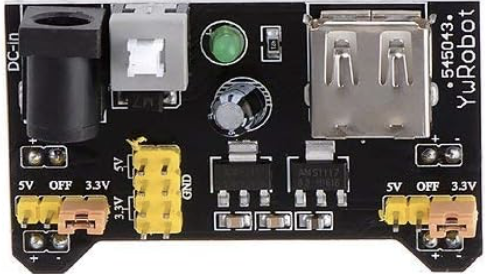
Figure 2 – HiLetgo 5pcs 3.3V 5V Power Supply Module for MB102 Prototype Breadboard DC 6.5-12V or USB Power Supply Module
ESP32 Placement
Many ESP32 development boards (notably those for the ESP32-WROOM chips) are “breadboard-unfriendly” because they are wide.
- Placement: Align the ESP32 so that the pins straddle the center Ravine.
- Note: You may likely only have one row of holes accessible on one side. If you can’t reach the pins, you may need to use male-to-female jumper wires to move the connections to an open area of the board.
Entering the Digital Workspace
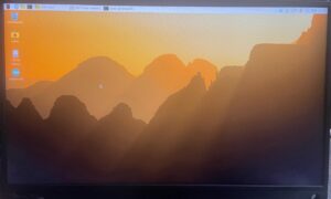
Once the “Raspberry” logo appears and the desktop loads:
- User Credentials: If prompted for a login, use the credentials provided by your instructor
- The system may be configured to boot directly to a user account and Home Screen..
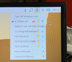
- WiFi Connection: Look at the Top Right Corner of the screen.
- Click the Blue/Grey Icon (two wedges).
- Select your classroom network and enter the password.
- The icon will turn blue once connected.
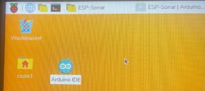
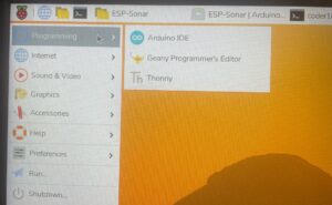
Launch the IDE: The software tool you will use for your projects is an Integrated Development Environment (IDE) that manages the files for your project, translates (I.e., compiles) your programs into instructions the ESP32 chips can execute, and uploads the instruction file to the chip. Find the Arduino IDE icon (the teal infinity circle) on the Desktop or in the Main Menu (the Raspberry icon in the top left) under Programming drop-down menu.
 |  |
Meeting the ESP32 Board
Now we connect the “brain” (the ESP32) to the “hub” (the RPi 400).
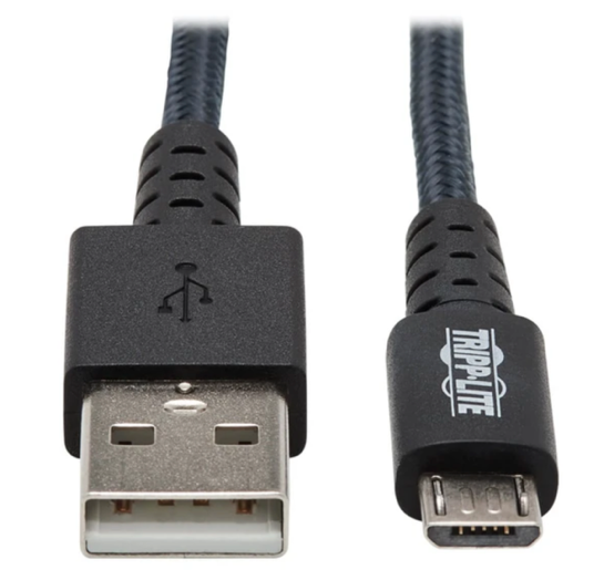
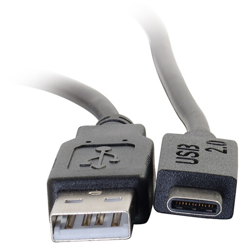
- Physical Connection: The USB connection is required to connect the development board to the IDE host computer to upload the compiled program and for debugging; it may additionally (and typically) provide power to the board during use. Development boards may use USB-micro or USB-C connectors. Use a compatible USB cable to connect the development board (e.g., ESP32-WROOM-32D) to one of the unused USB ports on the RPi 400. You should see a small red or blue LED light up on the ESP32 board to indicate it has power. Your USB cable will have a USB-A type connector on the end plugged into the Rpi400.
|
USB-A to micro-USB |
USB-A to USB-C |
- Identify the Serial Port used for the connection: In the Arduino IDE, go to Tools > Port.
- You are looking for something named /dev/ttyUSB0 or /dev/ttyACM0.
- If you migrate to a PC or MacOS platform, the serial ports will have different names. These names for the Linux-based refer to the serial-port driver software located in the /dev (I.e. device) directory in the Linux file system on the Rpi400.
- It is possible to have multiple boards connected, each with its own USB cable; in such case the final character will be a number assigned by the IDE host computer to identify different ports, e.g., /dev/ttyUSB0 and /dev/ttyUSB1.
- Action: Click it to select it. If you see multiple, unplug the board and see which one disappears, then plug it back in.
- You are looking for something named /dev/ttyUSB0 or /dev/ttyACM0.